Alternative Energy
Solutions to fit Budget, Expand Anytime, Enjoy Lower Energy Costs from Day One

DESIGN YOUR OWN SOALR HYBRID SYSTEM
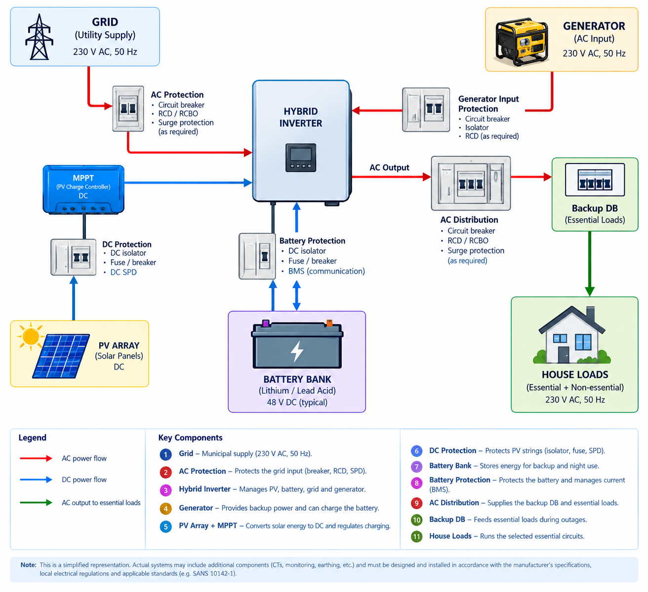
Below is a typical high level diagram, illustrating the essential components required to build a Solar Hybrid System, complete with rooftop PV panels and a backup generator for use during Eskom outages or load‑shedding events.
Below is a clear, high‑level overview, or checklist to help you structure your Hybrid Solar System.
Residential Hybrid Solar System Design Tutorial
-
A typical system looks like the diagram above.
There are several possible architectures. Some hybrid inverters have PV MPPTs built in; others use separate MPPT charge controllers. Some systems have separate grid and generator inputs. For example, Victron's Quattro architecture specifically supports two AC sources such as grid and generator.
-
This is the most important step.
Don't start by asking: "What size inverter should I buy?"
Rather start with: "What does the house actually need to run?"
Create a simple load schedule.
1 Refrigerator @ 200W for 10h = 2kW
15 Lights @ 10W for 5h = 0.50kW
1 WiFi AP @ 20W for 10h = 0.20kW
1 PC @ 150W for 5h = 1.50W
1 Washing Machine @ 700W for 1h = 0.7kW
1 Microwave @ 1.2kW for 0.5h - 0.60kW
1 Kettle @ 2kW for 0.5h = 1kW
Then calculate:
Daily energy
Eday=∑(W×hours)
So, for example:
7.5 kWh/day is required as calculated above
But energy consumption isn't enough.
You also need maximum simultaneous power.
-
Imagine these are operating simultaneously:
Refrigerator = 200 W
Lights = 150 W
TV = 150 W
Computer = 300 W
Kettle = 2,000 W
Microwave = 1,200 W
Total:
Ppeak=4,000WP or 4kW
Therefore you don't want a 3 kW inverter.
A sensible starting point might be a 5 kW inverter, subject to surge requirements, continuous ratings, temperature derating and the actual load profile.
You should similarly distinguishes between energy consumption and peak power requirement when designing residential backup systems.
-
This is extremely important for hybrid systems.
Don't necessarily put the entire house behind the inverter.
Create:
Essential / backup DB
For example:
Lights
Refrigerator
Wi-Fi
TV
Alarm
Security
Selected plugs
Garage door
Selected office equipment
And:
Non-essential DB
For example:
Electric geyser
Oven
Pool pump
Large air-conditioners
Electric heaters
Welder
EV charger
This dramatically reduces the inverter and battery requirements.
For example:
Whole house Peak: = 12 kW
Essential loads Peak: = 4 kW
A 5 kW hybrid inverter may therefore be perfectly suitable for the backup system, rather than needing a 12 kW inverter.
-
Look at four things.
A. Continuous output
If your calculated maximum essential load is: 4.0 kW
I'd normally look at: 5 kW minimum
rather than selecting a 4 kW unit with no margin.
B. Surge capacity
Motors and compressors can produce substantial startup currents.
Examples:
Refrigerator
Freezer
Pump
Air conditioner
Pool pump
Therefore check:
Continuous power
and
Peak/surge power
in the inverter datasheet.
C. Battery voltage
For residential systems, 48/51.2 V battery systems are common.
A 5 kW load at approximately 50 V means:
I = 5000W / 50Vdc =100A
After allowing for inverter losses, the battery current can be even higher.
This is one reason high-power residential systems should generally use a properly engineered higher-voltage battery architecture rather than trying to obtain large power from a small low-voltage battery bank.
D. AC inputs
If you're integrating a generator, this becomes critical.
You want an inverter/charger that can properly manage:
Grid + battery + PV + generator.
Some systems have separate AC inputs. Others use a shared AC input with generator detection/control.
-
Now calculate the battery.
Suppose:
Essential loads: = 1.5 kW average
Required backup: = 8 hours
Then:
1.5kW×8h=12kWh
But 12 kWh shouldn't necessarily be your nameplate battery size.
You need to account for:
Maximum depth of discharge
Inverter losses
Battery temperature
Battery ageing
Reserve SOC
Battery manufacturer's allowable continuous current
For example, if you want to use approximately 80% of the nominal capacity:
Battery = 12/0.8 = 15kWhBattery
Then you might choose something around: 15–16 kWh nominal rather than exactly 12 kWh.
Likewise you need battery sizing around required autonomy during a mains failure and remember that larger batteries provide longer backup autonomy.
-
This is a common design mistake.
A battery can have enough kWh but still not be able to deliver enough kW.
For example:
If Battery = 10 kWh it doesn't automatically mean: Battery can supply 10 kW.
Suppose the battery's maximum continuous discharge is: 100 A
At approximately 51.2 V then
51.2Vdc × 100A = 5.12kW
So approximately 5 kW is available before considering losses and manufacturer limits.
For a 5 kW inverter, that's potentially appropriate.
But if you install a 10 kW inverter with one 5 kWh battery
you could have a serious battery-current limitation.
-
For lithium batteries, check:
Battery voltage
Maximum charge current
Maximum discharge current
BMS communication
CAN/RS485 compatibility
Approved inverter list
Number of batteries allowed in parallel
Cable requirements
Battery fuse/breaker requirements
Don't simply assume:
"48 V battery = compatible with 48 V inverter."
The BMS communications and current limits can be equally important.
For example, Sunsynk's current guidance specifically requires checking battery compatibility and battery configuration, and its setup documentation specifies capacity and charge/discharge parameters.
-
Now we determine the PV size.
Suppose your house consumes: 20 kWh/day
and your design location effectively provides: 5 peak-sun-hours/day (harvesting Time)
The theoretical PV requirement is:
20 / 5 = 4kWp
But that's not what I'd necessarily install.
You need to account for:
Temperature
Dust
Cable losses
MPPT losses
Inverter losses
Panel degradation
Non-optimal orientation
Winter production
Battery charging
Cloudy weather
Therefore you might design around:
5–6 kWp
rather than exactly 4 kWp.
Actual PV yield should be calculated using local solar resource, orientation, inclination and shading, not a generic multiplier.
-
Now choose the panel.
For example: 550 W panel
If you need approximately: 5.5 kWp
then: 5500/550=10
So: 10 × 550 W = 5.5 kWp
But don't stop there.
You must design the strings.
-
Suppose the panel datasheet says approximately:
Voc = 50 V
Vmp = 42 V
Imp = 13 A
If you put 5 panels in series:
Voc = 5 × 50 = 250VVoc
Vmp = 5 x 42 = 210V
Five panels might therefore form: 5S
Two such strings in parallel: 5S 2P
Total: 10 panels
PV power: 5.5 kWp
But this is where professional design becomes important.
Check three things:
1. Maximum PV voltage
You must calculate cold-weather Voc, not simply use the panel's nominal Voc.
Cold temperatures can increase Voc. Standards explicitly warns that PV voltage rises at lower temperatures and that the MPPT's maximum PV voltage must not be exceeded.
2. MPPT operating range
Your string Vmp needs to sit comfortably inside the inverter's MPPT operating range.
3. Maximum MPPT current
Two strings in parallel: 13A + 13A = 26A
The inverter MPPT must be able to accept that current.
-
For an inverter with multiple MPPTs, don't automatically put everything on one MPPT.
This is particularly useful where:
Roof orientations differ
One roof is east-facing
Another is west-facing
Shading differs
String voltages differ
Avoid mixing substantially different orientations on the same MPPT unless the manufacturer's design rules permit it.
(See Figure 2)
-
Now we add the generator.
This is where hybrid systems become particularly interesting.
The generator needs to supply:
A. House load and potentially:
B. Battery charging at the same time.
For example:
House load: 3 kW
Battery charging: 3 kW
Required: 6 kW
Then a generator smaller than this could be heavily loaded.
Current guidance, for its systems, advises a generator with approximately twice the inverter's rated output to allow battery charging while supplying loads, although the exact generator requirement is model-dependent.
Don't apply that as a universal rule to every inverter. Always use the particular inverter manufacturer's generator specifications.
-
Suppose: 5 kW hybrid inverter
Possible generator: 8–10 kVA
But then we need to check:
Generator continuous kVA
Generator continuous kW
Power factor
AVR
Frequency stability
Voltage stability
Minimum loading
Maximum charging current
Generator input current limit
Neutral/earth arrangement
RCD/earth-leakage arrangement
Automatic start/stop capability
Generator guidance, for example, provides model-specific minimum generator sizes and warns that generator sizing must also account for charging and peak loads.
-
A sophisticated hybrid system can work like this:
Grid feeds Inverter
Generator feeds Inverter
Battery is a Load
House is a Load
Normal operation: PV → loads
Excess PV: PV → battery
If Grid is available:
Grid → supplement loads / charge battery according to settings
When Grid fails:
Battery → loads
Battery SOC becomes low Then Generator starts
Generator:
Generator → loads + battery charging
When Battery reaches target SOC:
Generator stops
If Grid returns:
Generator stops / grid resumes
This automatic generator strategy is a core feature of properly designed hybrid systems.
We describe exactly this approach: battery/inverter supply the loads first, then the generator can automatically start at a critical battery level and stop after recovery
-
A typical control strategy might be:
GRID FAILURE
▼
Battery supplies loads
▼
SOC declining
▼
SOC reaches 25%
▼
START GENERATOR
▼
Generator stabilises
▼
Transfer/enable generator input
▼
Generator supplies loads + charges battery
▼
Battery reaches 70%
▼
Stop generator
▼
Battery resumes
The actual SOC thresholds should be selected based on the battery, generator, load profile and manufacturer's recommended settings.
-
This is often overlooked.
The generator isn't simply another "230 V supply."
The inverter must be able to accept the generator's:
Voltage
Frequency
waveform
neutral arrangement
earthing arrangement
maximum current
The generator may also need:
AVR
electronic governor
dry-contact start
2-wire start
remote start module
Some hybrid systems can directly control generator start/stop; others require an external controller.
-
Your design will typically need appropriate protection for:
Grid → inverter
Main isolator
Circuit breaker
Surge protection where required
RCD/earth-leakage arrangements as applicable
Generator → inverter
Generator breaker
Isolation
Appropriate protection
Correct neutral/earth arrangement
Inverter → backup DB
Main breaker
RCD/RCBO arrangement as required
Surge protection where required
PV
DC isolator(s)
String protection where required
DC SPD where required
Correctly rated PV cable/connectors
Battery
DC-rated fuse/breaker
Battery isolator
Correct cable size
Appropriate busbars/distribution
BMS protection
Important: AC breakers and DC breakers are not interchangeable simply because their ampere rating is the same.
-
Cable sizing is not: "5 kW system = X mm² cable."
You cable size by calculate it from:
Current
Cable length
Installation method
Ambient temperature
Grouping
Voltage drop
Short-circuit rating
Cable insulation
Manufacturer requirements
For DC: I = P/V
For a 5 kW inverter at 51.2 V: I = 5000 / 51.2 ≈ 97.7A
After considering inverter losses, you may be above 100 A.
That is why the battery-to-inverter cable can be substantially larger than the PV string cable.
-
Suppose:
5 kW inverter
Battery: 51.2 V
Approximate DC current: I = 5000 / 51.2 = 97.7A
Allowing for inverter efficiency: I ≈ 103A
Now calculate the cable based on:
103 A design current
cable length
allowable voltage drop
installation method
temperature
protection device
Then select the cable and protection accordingly.
Never select the battery cable solely from the inverter's nominal power.
-
For a professional system, monitoring isn't an afterthought.
Monitor:
Grid power
PV power
Battery SOC
Battery voltage
Battery current
House consumption
Generator power
Generator runtime
Inverter temperature
Alarms
Faults
This lets you diagnose problems remotely and understand actual energy behavior.
Residential systems, for example, use GX monitoring to monitor battery SOC, consumption, PV, generator and grid parameters.
-
This is the sequence I'd recommend you use for your residential hybrid system:
1. SITE SURVEY
↓
2. LOAD LIST
↓
3. DAILY ENERGY kWh
↓
4. PEAK LOAD kW
↓
5. ESSENTIAL vs NON-ESSENTIAL LOADS
↓
6. BACKUP AUTONOMY
↓
7. BATTERY kWh
↓
8. BATTERY kW / CURRENT
↓
9. INVERTER kW
↓
10. PV ENERGY REQUIREMENT
↓
11. PV ARRAY kWp
↓
12. PV STRING DESIGN
↓
13. MPPT VOLTAGE/CURRENT CHECK
↓
14. GENERATOR kVA
↓
15. GENERATOR CONTROL
↓
16. AC PROTECTION
↓
17. DC/PV PROTECTION
↓
18. BATTERY PROTECTION
↓
19. CABLE SIZING
↓
20. EARTHING/BONDING
↓
21. MONITORING
↓
22. SETTINGS
↓
23. COMMISSIONING
↓
24. TEST GRID FAILURE
↓
25. TEST GENERATOR START
↓
26. TEST GENERATOR STOP
↓
27. HANDOVER
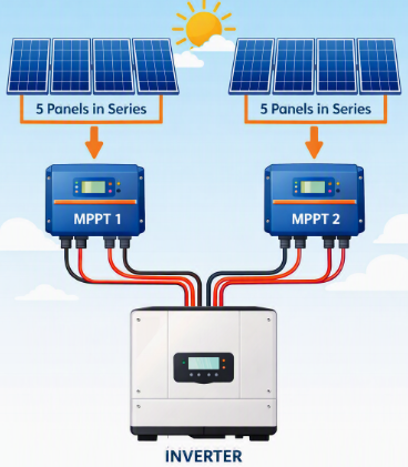
figure 2
Hypothetical Example
-
Given Specifications from Customer
Grid connected
5–8 hour backup
Solar during the day
Battery at night
Generator for extended outages
Essential loads only during outages
Load assessment
Average daily consumption: 18 kWh Essential backup energy: 10kWh
Essential peak load: 4.0 kW
Desired battery reserve: 20%
PV target: ~5 to 6 kWp
Inverter: ~5 kW class
Battery: ~15 kWh class
Generator: ~8–10 kVA class*
*Illustrative only; final generator size must be calculated against the selected inverter's charging capability and generator requirements.
-
When you're choosing actual equipment, create this table:
Hybrid inverter: kW, surge, battery voltage, MPPTs, AC inputs
Battery: kWh, usable kWh, kW, max current, BMS
PV panels: W, Voc, Vmp, Isc, Imp, temperature coefficient
MPPT: Max PV voltage, current, power, MPPT range
Generator: kVA, kW, AVR, start/stop, frequency
PV isolator: DC voltage/current rating
PV SPD: DC PV voltage rating/type
Battery fuse: DC voltage + interrupt rating + current
Battery isolator: DC Voltage/current
AC breaker: Voltage/current/breaking capacity
RCD/RCBO: Correct type and rating for application
Cable: Current, length, installation method, voltage drop
Monitoring: Meter/CT/shunt/GX/BMS communication
Earthing: Equipment + array + battery + generator requirements
-
If you're learning this as an installer / designer, remember these:
Rule 1
Load first. Equipment second.
Rule 2
kWh and kW are different.
Battery capacity is energy.
Inverter capacity is power.
Rule 3
Battery kWh isn't enough.
Always check battery maximum charge/discharge current.
Rule 4
PV voltage must be checked at temperature extremes.
Don't just add panel Voc numbers.
Rule 5
Generator size must consider charging + loads.
Not simply the inverter rating.
Rule 6
Protect every energy source.
Grid, generator, PV and battery each require appropriate protection.
Rule 7
Use the manufacturer's wiring diagrams.
Especially for:
Generator neutral
Earth bonding
CT placement
BMS communication
Parallel batteries
Multiple inverters
AC coupling
Rule 8
Commission by testing failure scenarios.
Don't just switch the system on.
Test:
Grid available
Grid failure
Battery low
Generator starts
Generator supplies load
Battery charges
Generator stops
Grid returns
PV production
Excess PV charging
High-load operation
Choose the option below that is most likely to represent your calculated household electrical load.